 Appendix
G
Appendix
G
Micro Oxymax respirometer
Student Instruction Manual for Micro-Oxymax
Micro-Oxymax software and calibration:
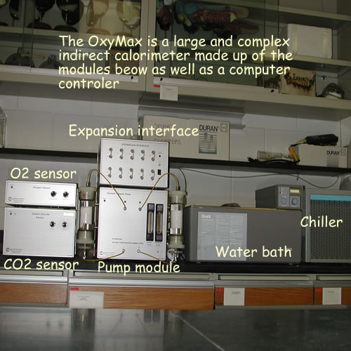
 The instrument is composed of four modules. An expansion interface that has the inlet and outle ports for each chamber on its front pannel. The OxyMax can not determine the oxygen and carbondioxide content of all of the chambers simultaneously. The unit is multiplexed and samples each chamber in turn. The primary function of this unit is to keep track of all 20 valves required to accomplish this. Lots of clicking sounds indicate that it is switching sample bottels. The expansion module also contains the gas dryer units and the electronic valves required to switch them in and out of the gas stream. The oxygen sensor can not tolerate any water and these units remove water with out removing carbon dioxide. Do not use the unit if the dryers look wet and nasty. They will ned to be recharged. The green power indicator should indicate that it is powered and it should not be turned off
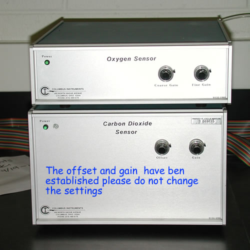 The oxygen and and carbon dioxide sensor modules house the electronic transducers that convert gas concentration into digital signals. Oxygen is quantified by passing a portion of the gas stream through a zinc/oxygen fuel cell. A voltage porportional to the oxygen concentration is generated, digitized and sent on to the computer. Carbon dioxide is quantified by injecting a portion of the gas stream into a miniature gas chromatograph and measuring the CO2 with an infrared detector. Prior to the lab, the Micro-Oxymax was calibrated using gas tanks with
pure gases ( N 2, O 2 and CO 2 ) at specific concentrations and left on to equillibrate. These calibrations proceedures
are complex and require training that is beyond the scope of this course. This instrument is mainained and calibrated by Tom Brewer.
The oxygen and and carbon dioxide sensor modules house the electronic transducers that convert gas concentration into digital signals. Oxygen is quantified by passing a portion of the gas stream through a zinc/oxygen fuel cell. A voltage porportional to the oxygen concentration is generated, digitized and sent on to the computer. Carbon dioxide is quantified by injecting a portion of the gas stream into a miniature gas chromatograph and measuring the CO2 with an infrared detector. Prior to the lab, the Micro-Oxymax was calibrated using gas tanks with
pure gases ( N 2, O 2 and CO 2 ) at specific concentrations and left on to equillibrate. These calibrations proceedures
are complex and require training that is beyond the scope of this course. This instrument is mainained and calibrated by Tom Brewer.
Operating instructions:
 Both the instrument and the water bath should set up and turned on the previous.
The water bath should be set
close to the operating temperature and monitored until it equikibrates at the set point. Low temps, in particular, require hours
to equilibrate and may require the addition of an antifreeze compound.
Both the instrument and the water bath should set up and turned on the previous.
The water bath should be set
close to the operating temperature and monitored until it equikibrates at the set point. Low temps, in particular, require hours
to equilibrate and may require the addition of an antifreeze compound.
- Select a chamber size that will result in 1 to 5g of animal/100ml gas space (for exotherms).
- Record the
weight and number of the animal(s) in each chamber. Be certain that the chambers are numbered with a permanent
ink sharpie. Add a few scraps of paper towel for cover and about 10ml of deionized water.
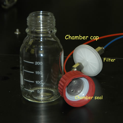
Note that there is a chamber seal inside chamber
covers. Inspect the seal to be certain that it is clean, dry, and undamaged then then
seal the beasts into the chamber.
- Put the organisms into their respective chambers along with a bit of shreaded paper towel for cover. If the animal is semiaquatic and subject to dessication you will need to add 5 or 10ml of water to keep the humidity up..
- Check to be certain that the cap has a sealing ring and that the rim of the bottle is clean. Screw the cap on firmly but avoid and demonstrtion of your grip strength as the rings are easily crushed.
- Note that the chamber lids are equiped with a pair of plastic tubes that interconnect
them with the instrument. The red line serves as the gas return and it runs uninterupted to the expansion
interface. The blue line serves as the gas outlet and it runs to a hydrophobic filter prior
to connecting to the expansion interface. It is critical that the outlet from the bottle pass through this filter prior
to the inlet port on the expansion interface. A single drop of water in the sensors will do serious damage to the sensors and
the filter acts to issure tht tiis does not happen.
- Note that the gas lines are color coded. The blue line has a hydrophobic filter . It is critical that this blue line is attached to the inlet port attached of the OxyMax. This will insure that no liquid water enters the instrument.
- Inspect the free end of the gas lines. If they are deeply groved, remove a few mm with a razor.
- Once they are sealed, hang a lead bagle over the neck of each chamber and place them in the water bath to equilibrate. They will float with out the bagle - make certain that they are stable and submerged.
- Make certain that the bath temperature probes are also in the bath and that the water circulation pump is on.
Hardware/software check
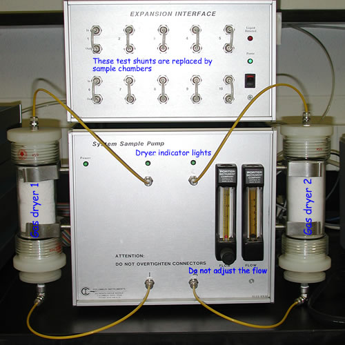
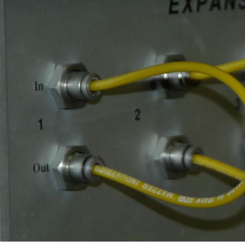 The expansion module should have bits of tubing sohrting out the input and outlet connectors for each chanel as shown in the photo to the right. The initial software/hardware checks are performed in this configuration.
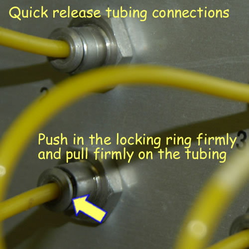
Connection is accomplished by simply inserting the tubing into the quickloc connectors. Disconection is accomplished by firmly pushing the locking ring in while firmly pulling the tubing out.
It is a good idea to connect all of the chambers and place them in the water bath at this point. This provides equilibration time while you are setting up the software.
- Remove the short shunt tubing from the expansion interface.
- Now connect the red line to the out port of the expansion chamber and the
blue line
from
the
hydrophobic
filter
to the
in port.
- Now double check. An incorrect color will trash the sensor.
Running the system setup software
- Create an experimental file
- The easy way press F1 from main menu
- Open an existing file for a similar experiment
- You will save it with a different name latter.
- Set up the experimental file. F1 will bring up a scanty help screen if you forget the commands.
- Chanels
- Path name for the experimental file
- There is no reason to change the path
- C:/OXYMAX
- File name
- This is a DOS app so you have 8 characters
- SIZEMT08 or ROACH08 would work
- The .DAT is automatically generated
- Sample interval for experiment
- Use the minimum permissable value
- Calculate this value for purging enabled and no dryer switching
- (# of chambers) * (6 min + refresh time) + 9 min
- Duration of the experiment in minutes
- use default = 0000
- which won’t end until you tell it to
- Purge sensors between measurements
- Select Y
- Purging will blow out any contamination from the previous sample
- It also increases the minimum sample interval.
- Refresh threshold
- Use +- 0.5%, It will probably never activate
- Refresh window 30 sec is appropriate for 250 ml chambers
- Starting Chamber to use Aux temp probe
- Automatically measure chamber volume in this experiment
- a good idea
- enter Y and variations in jar size are compensated for
- Sensor volume re-measure
- Point decimals are prefered in this country
- Gas measurement units
- your choice
- enter 1 for microliters
- Time units
- This can be converted later but hours are convenient
- Enter 2 for hours
- Normalize units
- post hock normalization more useful
- enter 0
- Measure oxygen or CO2 as +
- your choice
- but + will make graphing easier
- Yeild none of these are usful in this context
- Calculate % enter N
- Starting channel enter 0
- Number of chanels enter 0
- Enterning information on the chambers
- press page down
- enter data
- Escape and save the file.
Running the chamber tests
- Systems utilities and diagnosis can be accessed from the main menue with F5
- Run leak test. If any leakage is with in +/- 0.300 ml/min then
you can proceed, otherwise repair leak and retest just that chamber.(F5 - F4)
- The set up sequence should be. F1 or F2 then F3
if any changes were made other wise you should be running the experiment yu just set up
- Run head chamber volume determination. F5 - F2.
- Run experiment for 24 hrs or more. F8
After 24 hours stop the experiment, cleanup, and save data to the shared
drive.
- Select F9 Watch current experiment or F3 view previous experiment and convert the data for excell
- Control print will bring up the appropriate menu
- Put X's in the appropriate print boxes
- Configuration and comments
- Data interval 1-end
- Chamber 1-10
- Export to .PRN file
- Sort by chamber
- Print the file
(ROACH08.prn)
- Copy it to a jump drive
- Use your work station to move this file to the approprite Lab data folder (metaboBodySizeData) on Stushares.
- Parse the data into the existing data file (sizeMetab_08share.xlsx)
At this point you should copy the data file to your own drive so that you can work on it. Do not perform calculationms on the shared file on stushare.
Walter I. Hatch
wihatch@smcm.edu
August 12, 2012