 Laboratory
2Laboratory
2
Laboratory
2Laboratory
2We move our eyes constantly during our daily activities to keep our line of sight point-ed at a target of interest. In order to generate eye movements we have three antagonistic pairs of muscles that are attached to the globe of the eye. These three sets of muscles function to move the eyes horizontally (left versus right), vertically (up versus down) and torsionally (clockwise versus counter clockwise).
Electrooculography (EOG) is the electric transduction of combined eye movement. Without moving the head, a variety of horizontal and vertical eye movements encompass a visual field in which you can explore an image, utilizing spontaneous tendencies of gaze during conversations or reading. Sometimes, analysis of spontaneous gaze tendencies can indicate the attitude of a subject. For example, spontaneous movements towards the left are usually under control of the right hemisphere, which is generally associated with negative emotions.
Among motor activities that are easily observed and strongly reliant on cognitive function, saccades are of great interest. Saccades are rapid eye movements whose speed is proportional to the amplitude of angular displacement and can reach 800°/sec. They compose two of the three major stages in the ocular fixation process:
• initiation of movement, voluntary or not
• saccade corresponding to gaze displacement
• maintenance (micro-saccades) or suspension of fixation
For a given angular displacement, saccade duration is constant (see graph and table below). Its latency time, for visual stimulations, is around 200 ms. Despite any attempts by subjects, they cannot influence the speed of the saccade, but that speed can often vary as a function of attention level.
In the 1920's it was discovered that by placing electrodes on the skin
in the region of the eyes, one could record electrical activity that changed
in synchrony with movements of the eyes in the head. It was initially
believed that these potentials reflected the action potentials in the
muscles that are responsible for moving the eyes in the orbit.
However, it is now generally agreed that these electrical potentials are
generated by the permanent potential difference that exists between the
cornea and the retina (cornea-retinal potential, 10-30 mV: the cornea
being more positive). This potential difference sets up an electrical
field in the tissues surrounding the eye. As the eye rotates, the field
vector rotates correspondingly. Therefore, eye movements can be detected
by placing electrodes on the skin in the area of the head around the eyes.
Vertical movements of the eyes are best measured by placing the electrodes
on the lids, while horizontal eye movements can be best measured by placing
the electrodes on the external canthi (the bone on the side of the eye).
Limitations of the technique.
The assumption made when using this method of recording eye movements is that the movement of the electric field in the conducting tissues surrounding the eye is related, in a simple (usually assumed to be linear) way to movements of the eye itself. Due to the non-uniformity of these tissues and the shapes of the tissues surrounding them, this can only be an approximation to the biological reality. However, for horizontal eye movements within the range of 30 degrees, the potential measured is assumed to be linear to the actual movement of the eye in the orbit (in degrees of arc, see Fig. 8). The resolution of EOG is considered to be about 1 degree. Because it is a relatively simple technique, EOG is still commonly used clinically for testing eye movements in patients.
For a fixed eye position, the EOG is far from being constant in magnitude, but can be influenced by a number of external factors. These factors include 1) the noise generated between the electrodes' contacts and the skin, 2) the metabolic state of the tissues (pO2, pCO2, and temperature), 3) visual stimulation, and 4) contraction of the facial muscles. In addition, recorded EOG, particularly for vertical eye movements, is quite sensitive to movements of the eye lids. In summary, there are a number of external factors that can complicate the interpretation of the EOG, and for that reason EOG is considered to be highly sensitive to artifacts. Artifacts, which can be induced through the contact between the electrode contacts and the skin, can be minimized by reducing the resistance between the electrodes and the skin. For this reason, the subject should be sure to have thoroughly scrubbed his/her skin with the alcohol prior to attaching the EOG electrodes.
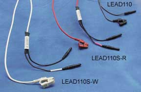
Your experiments will be recorded with silver/silver chloride surface electrodes. These electrodes have been specially designed for recording biological potentials.
 Surface electrodes: Skin Preparation and Placement
Both skin preparation and electrode are important to the production of a clean signal
 Wait at least 5 minutes once the preceding exercises have been completed,
and then connect the EOG electrodes to the pinch lead set. Attach the
red shielded cable to the right electrode, the black shielded cable
to the left electrode and the unshielded ground to the reference electrode
in the center of the head.
Wait at least 5 minutes once the preceding exercises have been completed,
and then connect the EOG electrodes to the pinch lead set. Attach the
red shielded cable to the right electrode, the black shielded cable
to the left electrode and the unshielded ground to the reference electrode
in the center of the head.
 Plug the other end of the cables into the electrode extension cable (BSCBL8). The
red wire into Vin+ socket (white)and its shield into the shield socket
(green), The black cable into the Vin- socket (black) and its shield
to the shield socket (dark red) and the unshielded reference wire into
the ground socket (brown). There is no shield for the reference
electrode.
Plug the other end of the cables into the electrode extension cable (BSCBL8). The
red wire into Vin+ socket (white)and its shield into the shield socket
(green), The black cable into the Vin- socket (black) and its shield
to the shield socket (dark red) and the unshielded reference wire into
the ground socket (brown). There is no shield for the reference
electrode.Note: the subject should not wear eyeglasses during eye movement recordings. Can't see the screen with out your glasses? Use another set of eyes. Contacts are ok; its the metal frames acting as anteing that are the problem.
Eye movements fall into two main categories: 1) Eye movements that function to stabilize the position of the eye in space during head movements (Reflex eye movements) and 2) Eye movements that function to redirect the line of sight to follow a moving target or to attend to a new target of interest (Voluntary eye movements). We will explore both.
Voluntary Eye Movements - SACCADES: Saccadic eye movements (saccades) move the eye rapidly to a specific target of interest in visual space. The word saccade originates from the French term for "jerk", named so to reflect the great speed at which these eye movements occur. Eye movements are generally described in terms of the angle (in degrees) that the eye has rotated. Saccades last for only a fraction of a second and can reach speeds up to 900 deg/s.
Saccades are under voluntary control and can be made in the dark, or with the eyes closed. During our daily activities, we constantly generate saccadic eye movements to scan our visual surroundings. When viewing an object of interest, we make saccadic eye movements to specific features of the image in order to "analyze" it; in the case of the human face, saccades are made primarily to areas containing the eyes. Likewise, while reading we generate small saccadic eye movements to move from word to word, phrase to phrase, and line to line. As in the previous experiment we need to first configure the computer to acquire this signal.
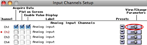
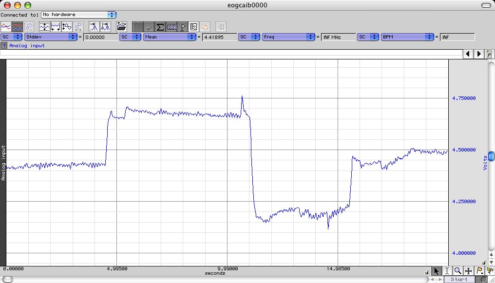 Have
the subject first look straight ahead, then repeatedly look as far to
the left, and then as far to the right as they can. If the signal is
very small, increase the gain until it fits appropriately with in the "green guidelines"
Have
the subject first look straight ahead, then repeatedly look as far to
the left, and then as far to the right as they can. If the signal is
very small, increase the gain until it fits appropriately with in the "green guidelines"Now that you know that your maximum and minimum values will not exceed the input range for the ADC, you are configured to record your EOG but The units for EOG are degrees and the input to the MP35 is volts. In order to determine the relationship between the amplitude of the measured voltage and the actual eye movement generated by the subject, it is necessary to construct a calibration curve. There is no fundamental difference between this calibration curve and those you constructed in POB.
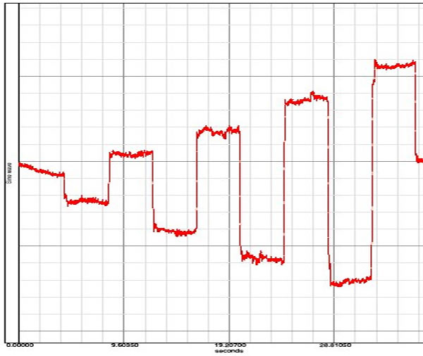
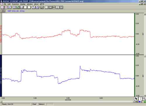
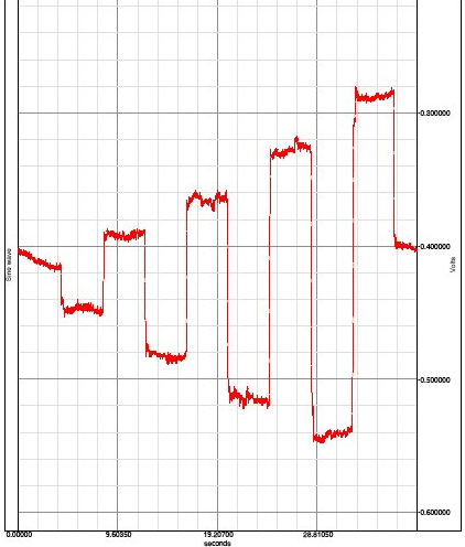
Processing the data
You will need to determine the mean input voltage and its standard deviation that resulted from each of the calibrated angular deviation of the eyes. The distance the target moves along the horizontal axis was calculated from the sine of the required calibration angle, and the length of the adjacent side of the triangle (the 20cm pointer). The targets are placed at 0 degrees (intersection of blue lines and 10, 20,30, and 40 degrees on either side of 0 movement to the left is assigned a positive angle while movement to the right was assigned a negative value to correspond the voltages produced when the eye with a positive cornea is rotated.
What is the measured value for the center target? This value represents the offset reading for the electrodes, at this subject at this time.
 Plot the data (angle vs EOG potential delivered to the MP35 in mV ) The graph template is here or on stushares
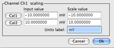 Enter ± 20 degrees in the "scale value boxes for cal 1 and cal2. It doesn't matter if the - or positive value is first only that it is paired with its calibrated value.
Humans and other primates can follow a moving visual target of interest by generating voluntary smooth pursuit eye movements. The smooth eye movements which are generated are designed to keep a small moving target on the center of the receptive surface of the eye so that it is viewed with the greatest accuracy. In the absence of a moving visual target, it is not possible to generate smooth pursuit eye movements. Therefore, it is impossible to generate smooth pursuit eye movements with the eyes closed, in the dark, or when viewing a stationary visual scene.
Horizontal pursuit
Pursuit with out target
Pursuit of knowledge
.jpg)
Vestibule- ocular reflex
Un blurred vision is only possible if the eye is stationary (fixed) with
respect to a viewed object. The vestibulo-ocular reflex (VOR) is an important
mechanism by which un blurred vision is made possible during head movements
that are generated during every day activities such as walking and running.
For example, if the head is turned to the left, this reflex causes the
eyes to move to the right (i.e. in the opposite direction of the head
movement). The oppositely directed eye movement occurs at the same velocity
as the head movement, and therefore generates an eye movement which keeps
our line of sight fixed on the same point in visual space both during
and following the movement.
During short head movements, these compensatory eye movements remain well within the mechanical limits of eye rotation. However during large amplitude head rotation, the eye can reach its limit of excursion long before the head movement is completed. Consequently, during this condition, an additional feature is added to the VOR: when the eye reaches an extreme position, it is rapidly flicked back to a new starting position. From this new starting position, the eye then continues a new cycle of compensatory movement during continuing head movement. The resulting "saw tooth" pattern of slow compensatory/ rapid resetting eye movements (slow phases and quick phases respectively) are referred to as vestibular nystagmus.
Saccade speed sorry the led's went missing and we can not perform this experiment They can be replaced if you want to incorporate them into a project
But,
You can still determine the rotational velocity of your eyes (rpm) from data on your calibration run. Reopen the calibration run and using that data calculate the rotational velocity. I am not going to provide the formula so think about it for a min and ask yourself what you want to know (RPM = revolutions per min) and write out the formula.
- What data does your graph contain?
- How many degrees in an R?
- What does per mean
- How many seceond in a min.
- What is your formula for RPM calculated from the data at hand.
Remember that the X axis is in seconds not min so yo need to adjut your formula
If you can time the appearance of a target you can determine how long it took to move your eyes to acquire it.
Adding a second coupled electrode set will permit tracking the exact path of a visual examination of an image. While this does not provide much additional physiological information, it does provide psychological information like attitudes or areas of specific interest. This is optional but it is cool.
Remember both skin preparation and electrode are important to the production of a clean signal. Prepare electrode sites as above.
 leave the electrodes to the side of each eye untouched. Leave the electrode being the ear. It will replace one of the forehead electrodes in the image below.
 Have the subject sit facing the computer monitor.
Walter I. Hatch
wihatch@smcm.edu
September 10, 2012